


Todos os Produtos
-
 Bruno NascimentoObrigado pela sua ajuda e apoio contínuos para nos fornecer produtos de alta qualidade e acessíveis.
 -
 Ehsan SalmariA resposta rápida e a atitude profissional tornam a nossa cooperação mais suave!
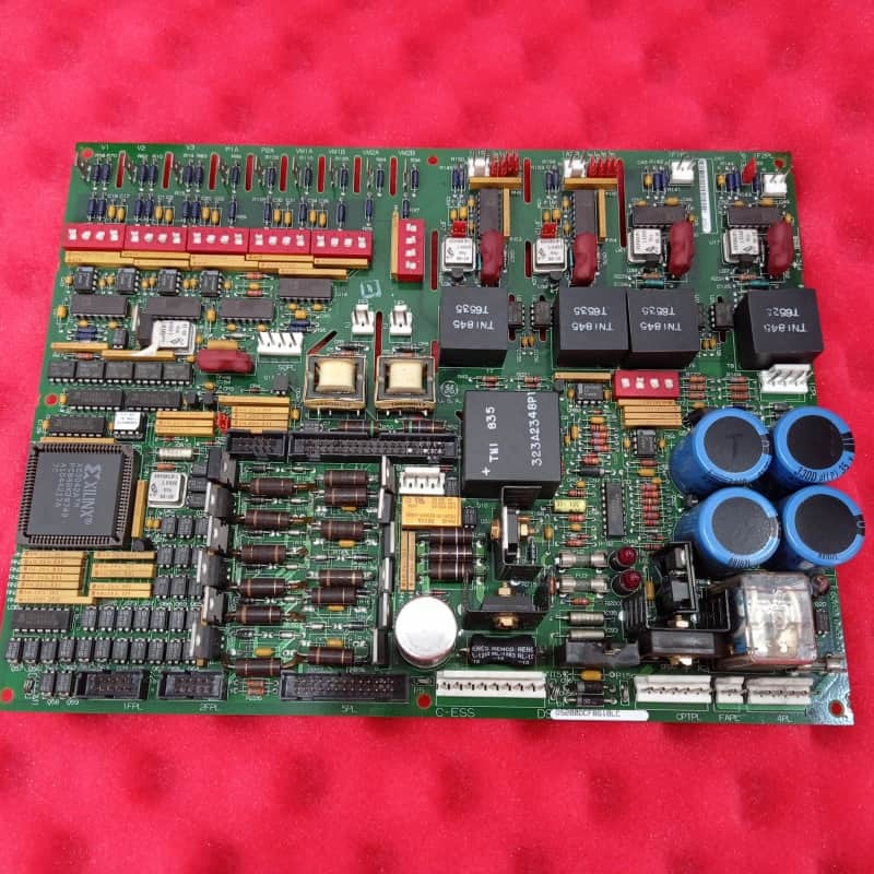
General Electric DS200DCFBG1B DC DC SONDA FEEDEDBACK TURBINA E APLICAÇÕES DE DIRSAGEM


| Lugar de origem | EUA |
|---|---|
| Marca | GE |
| Certificação | COO |
| Número do modelo | DS200DCFBG1B |
| Quantidade de ordem mínima | 1 |
| Preço | $1800 |
| Tempo de entrega | 5-7 dias |
| Termos de pagamento | T/T. |
| Habilidade da fonte | 999 |
Detalhes do produto
| Nome | General Electric DS200DCFBG1B DC DC SONDA FEEDEDBACK TURBINA E APLICAÇÕES DE DIRSAGEM | ID do produto | DS200DCFBG1B |
|---|---|---|---|
| Série | Mark v | Garantia | 1 ano |
| Profundidade líquida do produto/comprimento | 330mm | Altura líquida do produto | 200 mm |
| Peso líquido do produto | 2kg | Largura líquida do produto | 100mm |
| Destacar | Placa de Feedback da Fonte de Alimentação DC do DIP Switch SW6,Placa de Feedback de 12 Jumpers,Placa da Fonte de Alimentação de Entrada 38 VAC/115 VAC |
||
Descrição de produto
General Electric DS200DCFBG1B Painel de Feedback de Fornecimento de Energia CC Turbina Crítica e Aplicações de Acionamento
Descrição do produto:
A General ElectricDS200DCFBG1Bé um painel de feedback de alimentação em corrente contínua concebido para aplicações críticas de turbinas e motores, incluindo as séries EX2000, DC2000 e AC2000.Conversão de potência de entrada de um transformador de potência de controlo em várias tensões de CC reguladas para operar o sistema de accionamento e os ventiladores do gabinete.
Características principais:
O papel principal da placa é gerar e distribuir várias fontes de alimentação de nível de controle, incluindo +5V, ±15V e ±24VDC. Além da conversão de energia,integra circuitos de monitorização sofisticados que rastreiam parâmetros essenciais do sistema, como corrente e tensão da armaduraInclui também os circuitos de driver para os geradores de pulso de porta SCR do campo do motor.
Uma característica definidora do DS200DCFBG1B é o uso de circuitos de oscilador controlado por tensão (VCO).tensão de ponte de saída, e os sinais de milivolt do campo e da armadura são desviados para sinais de frequência proporcional (0-500 kHz).Estes sinais de frequência digital são então transmitidos para o SDCC mestre ou placa de controle LDCC para processamento, fornecendo um feedback fiável sobre o estado operacional do motor.
A placa é altamente configurável através de doze saltadores e sete interruptores DIP, permitindo opções específicas do cliente, embora estas sejam tipicamente configuradas na fábrica.Incorpora características robustas de diagnóstico e protecçãoO estado da fonte vital de +5VDC é indicado pelo sinal /PSEN, que pode desencadear uma reinicialização do microprocessador na placa de controlo se a tensão não estiver regulada.a placa é protegida por fusíveis (FU1, FU2, FU3) para as suas saídas de energia, com indicadores visuais claros LEDs CR51 e CR55 para fusíveis CC e uma luz de néon LT1 para o fusível AC para identificar rapidamente as falhas.
![]()
Produtos recomendados
-
VIDEO
